Friday 28 December 2012

Mobile Terminated Roaming Retry for LTE CSFB


One of the many issues with LTE Circuit Switched Fall Back (CSFB) is what happens when the UE falls back on the target RAT (can be 3G or 2G, operator defined) and the LAC is not the same as the one the UE is registered on through the Combined Attach procedure in LTE. This typically occurs on the borders of Location Areas (LA) and Tracking Areas (TA) or when the target layer is 3G and the UE can only acquire 2G (e.g. indoors).

In these cases, a Mobile Originated CS call would experience a delay as the UE would first have to perform a LAU procedure on the target RAT followed by the subsequent call setup procedure.

A Mobile Terminated CS call on the other hand would fail as the call has already been routed to the "old" MSC (i.e. the one the UE registered on though the Combined Attach procedure) but the UE finds itself in the LAC of a different, "new", MSC.

To prevent this happening two 3GPP defined procedures can be re-used. The first one is called Mobile Terminated Roaming Retry (defined in rel.07) and the second one is called Mobile Terminated Roaming Forwarding (defined in rel.10). Both of these require an upgrade to the CN elements involved in the call setup procedure.

It is interesting to note, that both of these procedures were defined originally to handle the (rare) occasion of a UE being paged in one LA but at the same time moving through a LA border and thus performing a LAU procedure on a different MSC than the one being paged on.

For this post we will have a closer look at the Mobile Terminated Roaming Retry (MTRR) procedure.

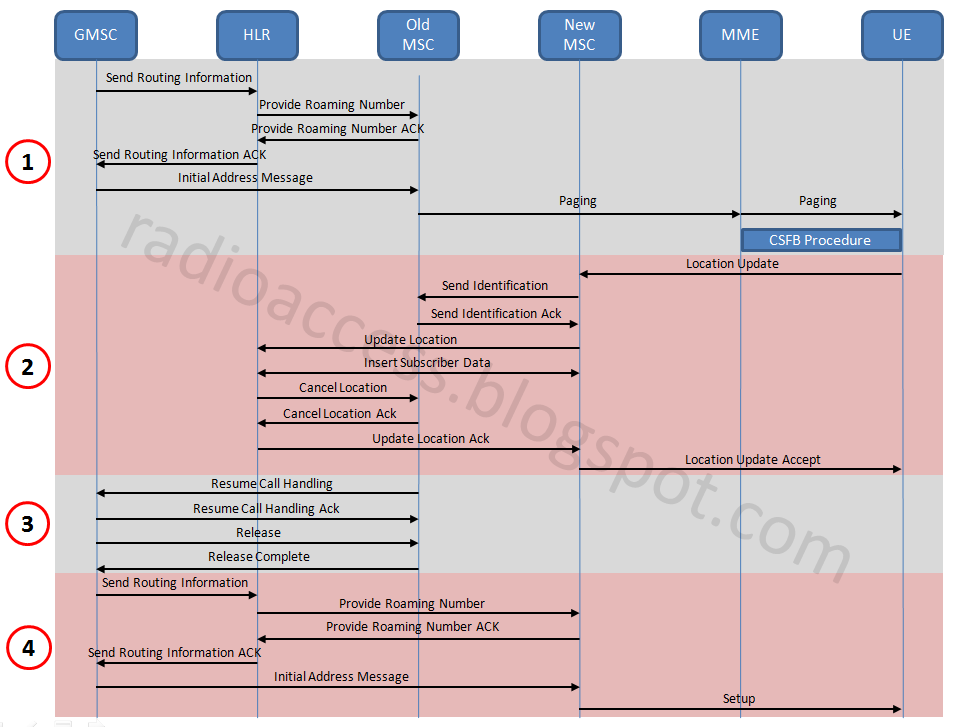
The signalling flow is shown above (click to enlarge) and can be broken down into 4 distinct phases.

During phase 1, a MT call comes through the GMSC which initiates the MAP procedures to inform the MSC the UE is registered on (through the Combined Attach procedure). The MSC contacts the MME through the SGs interface which pages the UE. The paging action initiates the CSFB procedure and the UE is directed towards the target RAT.

Under normal circumstances the UE would fall back on the LA it registered on and would send a Paging Response. In this case however the UE falls back on a different LA and thus has to perform a LAU procedure. This is shown in phase 2, as is the subsequent procedure to transfer the UE subscription from the "old" MSC to the "new" one.

This is also where the call setup procedure would fail as the "old" MSC would not have the ability to inform the GSMC that the UE has changed MSCs.

With MTRR however the "old" MSC informs the GMSC through the Resume Call Handling procedure that the call setup procedure should be repeated by contacting the HLR once more. This is shown in phase 3 of the signalling flow.

Finally, phase 4 is a repeat of phase 1, but this time the GMSC contacts the correct "new" MSC and the call setup procedure is successful.

It is also important to note that during the LAU procedure in phase 2, the UE populated an IE indicating that a CS MT call was in progress. This ensures the new "MSC" keeps the signalling link towards the HLR for the subsequent signalling exchange in phase 4.

Obviously this whole procedure would also add a couple of seconds more on the overall call setup time, which due to the general CSFB procedure is already longer that a "native" CS call setup in 2G/3G.

In the next few posts I will look at the second option, MTRF, and also at a completely different approach that uses an inter working function between the MME and MSC in order to avoid any upgrades in the legacy CS network.

Tuesday 25 December 2012

RRC state machine in Vodafone Greece


As I travel I find it interesting to look at how operators configure their networks. I travel to Greece quite often and have noticed that for quite some time now, Vodafone Greece do not use CELL_FACH or CELL/URA_PCH on their network.

This is illustrated in the log extract above. A PS Radio Bearer is established with no subsequent data transfer. After 20s of inactivity the RRC Connection is released and the UE returns to IDLE. So essentially the RRC state machine that Vodafone Greece use consists of two states only. CELL_DCH and IDLE. This is quite strange as there are a number of advantages in using CELL_FACH and CELL/URA_PCH. Obviously for small amounts of data (keep alive messages etc) CELL_FACH can be used without consuming dedicated resources. When there is no data transfer, CELL_PCH or URA_PCH can be used where no radio resources are consumed, the UE can go into DRX and at the same time allow for a fast transition (i.e. low latency) back to CELL_DCH if data transfer is required.

I find it hard to think of a reason why someone would configure their network this way, as it seems very signalling intensive and high latency. Unfortunately my test device did not support Fast Dormancy rel8 so I could not see how the RNC would react if the UE indicated it had no further data to transfer.

Friday 14 December 2012

What is 3G?


Ok, so my posts are usually a bit more detailed than this, but I was looking at the Google Search stats for 2012 and it seems the question "What is 3G" was the 3rd most searched "What is..." type question (1st was love and 2nd was iCloud in case you are wondering). So here is my attempt to explain the mysterious 3G..

3G refers to the 3rd Generation mobile technology standard. But if we are talking about the 3rd Generation, what were the 1st and 2nd?

The 1st Generation was based on analogue technology (like your FM radio) and appeared around the 1980's in a few countries. The mobile phones were enormous, the batteries even bigger (sometimes external to the handset) and they were very expensive. I imagine very people reading this post ever used a 1st Generation analogue mobile phone. 1st Generation networks are a thing of the past now and none exist anymore (at least in the so called "developed" countries).

The 2nd Generation was based on digital technology (like your digital TV) and appeared around the beginning of the 1990's. The most popular 2G standard is called GSM (Groupe Speciale Mobile) and is still incredibly popular today. I imagine the vast majority of people reading this post have used and are still using GSM. 2G technology standards were initially developed to support voice calls. The transfer of data was a bit of an after thought and the GSM standard was further enhanced with GPRS (General Packet Radio Service) and then EDGE (Enhanced Data rates for GSM Evolution).

So now we come back to 3G. The 3rd Generation was also based on digital technology and appeared around the beginning of the 2000's. The most popular standard is called UMTS (Universal Mobile Telecommunications System) and it too has proven incredibly popular. The main benefit of UMTS over GSM is that is supports much higher data rates so the web browsing, downloading, tweeting etc happen much faster. The UMTS standard was further enhanced with HSDPA (High Speed Downlink Packet Access) and HSUPA (High Speed Uplink Packet Access) to further increase the data rates possible. Of course if all you are interested is making voice calls and sending some text messages, there is not much benefit in 3G as 2G will do that just fine.

So 1G has disappeared and we are left with 2G and 3G. Most phones today support both standards and most operators, support both networks. These can be thought of as layers, like the graphic above. A dual standard phone will have a preference to camp on the 3G layer (point 1 above). When the 3G layer is not available (typically 3G networks use higher frequencies and thus don't propagate as far) the mobile will transition to the 2G layer. This can happen both in idle and during a voice call or data session (point 2 above). Once 3G coverage improves the mobile will re-select back to the 3G layer.

As an end user you can tell which standard/layer you are using by looking at the icon next to the signal strength bars on your phone. Unfortunately the actual icon itself is not standardised so mobile phone manufacturers usually pick from a collection. The possibilities are:

For 2G it is typically "2G", or sometimes just "G" or sometimes "E" (for EDGE), or "O" if you are using an iPhone (Apple, go figure..)

For 3G it is typically "3G", or sometimes "H" (for HSDPA/HSUPA), or "3G+" (again for HSDPA/HSUPA), or even "H+" (for some further enhancements to HSDPA)

A bit confusing, but you get the idea.

We are now at a time where 4G networks have started appearing. These are based on a standard called LTE (Long Term Evolution) and support even higher data rates. This can be thought of as just another layer on the graphic above, and a 4G capable phone will have a preference to camp on the 4G layer and when that is not available on the 3G layer and when that is not available on the 2G layer.

That is my attempt at answering "What is 3G?". Hopefully it makes some sense!

Sunday 25 November 2012

LTE RF conditions classification


It is common sense that the performance of any wireless system has a direct relationship with the RF conditions at the time. To aid with performance analysis then, we typically define some ranges of RF measurements that correspond to some typical RF conditions one might find themselves in.

When it comes to LTE, I came across the above table that presents a good classification. The source of this table is a EUTRAN vendor and has been complied during the RF tuning process for a major US operator. Of course there are no rules as to how various RF conditions are classified, so different tables will exist but to a great extent you can expect them to align.

In this particular example, three measurement quantities are used. RSRP (Reference Signal Received Power), RSRQ (Reference Signal Received Quality) and SINR (Signal to Interference & Noise Ratio).

RSRP is a measure of signal strength. It is of most importance as it used by the UE for the cell selection and reselection process and is reported to the network to aid in the handover procedure. For those used to working in UMTS WCDMA it is equivalent to CPICH RSCP.

The 3GPP spec description is "The RSRP (Reference Signal Received Power) is determined for a considered cell as the linear average over the power contributions (Watts) of the resource elements that carry cell specific Reference Signals within the considered measurement frequency bandwidth."

In simple terms the Reference Signal (RS) is mapped to Resource Elements (RE). This mapping follows a specific pattern (see below). So at any point in time the UE will measure all the REs that carry the RS and average the measurements to obtain an RSRP reading.


RSRQ is a measure of signal quality. It is measured by the UE and reported back to the network to aid in the handover procedure. For those used to working in UMTS WCDMA is it equivalent to CPICH Ec/N0. Unlike UTMS WCDMA though it is not used for the process of cell selection and reselection (at least in the Rel08 version of the specs).

The 3GPP spec description is "RSRQ (Reference Signal Received Quality) is defined as the ratio: N×RSRP/(E -UTRA carrier RSSI) where N is the number of Resource Blocks of the E-UTRA carrier RSSI measurement bandwidth."

The new term that appears here is RSSI (Received Signal Strength Indicator). RSSI is effectively a measurement of all of the power contained in the applicable spectrum (1.4, 3, 5, 10, 15 or 20MHz). This could be signals, control channels, data channels, adjacent cell power, background noise, everything. As RSSI applies to the whole spectrum we need to multiple the RSRP measurement by N (the number of resource blocks) which effectively applies the RSRP measurement across the whole spectrum and allows us to compare the two.

Finally SINR is a measure of signal quality as well. Unlike RSRQ, it is not defined in the 3GPP specs but defined by the UE vendor. It is not reported to the network. SINR is used a lot by operators, and the LTE industry in general, as it better quantifies the relationship between RF conditions and throughput. UEs typically use SINR to calculate the CQI (Channel Quality Indicator) they report to the network.

The components of the SINR calculation can be defined as:

S: indicates the power of measured usable signals. Reference signals (RS) and physical downlink shared channels (PDSCHs) are mainly involved

I: indicates the power of measured signals or channel interference signals from other cells in the current system

N: indicates background noise, which is related to measurement bandwidths and receiver noise coefficients

So that is it! I have also included a real life measurement from a Sierra Wireless card that includes the above mentioned metrics so you can see what is the typical output from a UE. Using that and the table above you should be able to deduce the RF condition category it is in at the time of measurement.


Sunday 18 November 2012

Category 4 LTE UEs in the market


It is interesting to see that the first category 4 LTE UEs are appearing in the market. Up to now the vast majority (if not all) of LTE devices have been category 3. The device in question is Huawei's E3276 USB dongle. Category 4 LTE UEs can reach theoretical physical layer DL throughputs of up to 150Mbps. The uplink throughput stays the same at 50Mbps.

The E3276 is also LTE penta-band capable (LTE FDD 800/900/1800/2100/2600) which means that it will operate in pretty much every country that has launched LTE.

The complete 3GPP release 8 LTE UE category table can be seen below.

Moving to the next category, 5,  is not going to be that easy as it requires 4x4 MIMO in the DL. This will mean operators will need to deploy an additional 2 antennas on the base station and UE vendors will need to squeeze another 2 antennas in the device. Possible on a tablet but anything smaller is going to be a challenge. In case you are wondering the increase in the uplink performance of a category 5 device is due to the use of 64QAM as opposed to 16QAM.

Wednesday 7 November 2012

Unhappy with 4G? Lock to 3G!

For years now buying a 3G handset and locking it to 2G has been quite popular. As reported here this was mainly done to get around poor battery life in 3G. Of course this would have an obvious impact on data performance as GPRS/EDGE networks struggle to deliver anything faster than a couple of hundered of kbps at best. From an operator (carrier for our US readers) point of view this was bad as it meant the legacy 2G network was still seeing quite a lot of traffic.

Considering the above it was interesting to see what the options are for 4G capable devices. A screenshot from the Network Mode menu of a Samsung SIII LTE is shown below.


As you can see gone is the option to lock to 2G and now the two options are either 2G/3G/4G (i.e. auto) or 3G only. I guess the option to disable 4G has to be there, from a battery life point of view, stability of early 4G networks and the problems with support for voice calls. But at least in my opinion the second choice should be 3G/2G as opposed to 3G only. I guess this will change depending on the device manufacturer so it will be interesting to see what others do.

Tuesday 6 November 2012

Chance encounter with a femto cell


I was recently performing some drive tests in a busy city centre and came across a femto cell in closed access mode. It was a chance encounter and I was only alerted to its presence by the automated TEMS voice indicating a failed Location Update. The first thing to note as indicated by the map below, is that this location in theory should have perfect coverage. What this shows (perhaps of no surprise) is that even in city centres, coverage holes do exist and people are forced to install femto cells for in-house coverage.


The second thing to note is that this is probably the worst place to install a closed access femto cell. The road is a busy one and to make things even worse there is a bus stop just outside! The amount of failed location updates must be in the in the hundreds if not thousands per day as a continuous stream of cars, buses and pedestrians pass through. A true closed access femto cell nightmare. The signalling trace below, shows the procedures involved as the UE tries to camp on the femto cell and gets rejected (cause code 13).

The time elapsed from reselecting the femto cell, failing to perform a LAU, returning to the macro and performing a further LAU/RAU (not shown in the trace) was approx. 6 seconds. So quite a large "outage" from the customers point of view. From a femto point of view we can expect the LAU attempt to be handled locally (i.e by the femto itself). The subsequent LAU/RAU back on the macro however is handled normally and as such the load on the core network is measurable. So what can be done is cases like this? Femto cells can be installed anywhere so how can the operator protect themselves? A few things come to mind. First detecting the problem. This could be easily solved by looking at failed LAU attemtps counters from the femto (if the manufacturer has implemented them). For an even more obvious detection method an NMC alarm could be created for when the amount of failed LAUs exceed a particular threshold. Once the problem femto is detected its CPICH could be reduced so it is not over-propagating into the street.

Sunday 4 November 2012

WCDMA code tree fragmentation and what to do about it

Managing the downlink code tree in WCDMA is an important Radio Resource Management function. As a WCDMA system starts accepting traffic, various branches of the code tree will be blocked. Ensuring that the code tree is as compact as possible enables the system to freely allocate higher branches (lower SF). For HSDPA heavy networks this is key in ensuring the scheduler has at any TTI the maximum SF16 available.

Most UTRAN vendors manage this during the set-up phase. So for example a CS12.2kbps voice call (SF128) will get the left most SF128 available. This ensures that the right hand side of the code tree can be allocated to HSDPA. In high traffic situations however, as calls continuously get set up and released, even this approach might lead to fragmentation. As an example assume that at time X, SF128,48 was the left most SF128 available and this get allocated to a UE. At time X+1 however, it might be that a number of connections have been released and SF128,30 is now available. If however the original call on SF128,48 is still ongoing that space between 48 and 30 cannot be utilised.

A solution to this problem is to use dynamic code tree management which is what this network is using. As the trace extract shows at RRC Radio Bearer Setup that UE was allocated SF128-37.


Then as time progresses, a number of calls get released and the RNC instructs the UE to switch to SF128-30 as this is the left most SF128 available. This switch is signalled to the UE using the RRC Physical Channel Reconfiguration message, as the spreading operation in WCDMA is covered by the physical layer.


This procedure can then further repeat itself, depending on how much traffic there is and how long the connection lasts.

Wednesday 13 June 2012

Apple announce FaceTime over 3G/LTE on iOS6


At the recent Apple WWDC it was announced that on iOS6 users will be able to use FaceTime over the cellular network. I should point out that this has been possible for a while with a jailbroken iPhone but in iOS6 it will be available as standard.

Now video calling has been possible in 3G since the beginning, but as most people know it never had much success. Some device manufacturers actually even removed the capability from the menu as years progressed. I guess the reasons for it failing were many, but for sure the quality aspect of it had a big impact. Video calls over 3G were handled by a circuit switched 64kbps connection and no matter how good the codecs, trying to send video and audio over that bandwidth just didn't work.

Things have obviously evolved since and now with HSPA(+) and LTE there is quite a lot a bandwidth over the air interface. But how much bandwidth does FaceTime require anyway? To find out I hooked up my iPhone to a Wi-Fi access point that I can monitor and produced the graph below.


The x axis shows bits, so on average the bandwidth utilisation is around 400kbps. I should point out that for this FaceTime call the background was mostly static. As you can see at the beginning of the call there was some movement and the utilisation exceeded 500kbps. This is due to the way video codecs work where only the delta between frames is sent (roughly speaking).

From an network operator point it will be interesting to see how the quality aspect of it is handled. Even though the air interface bandwidth with HSPA(+) and LTE is very high, it is still a shared medium, with mobility, fading, noise, etc which could make the user experience quite poor in some situations.

One approach could be to offer a best effort service (which almost all operators do for data at the moment) but another approach could be to offer some level of QoS. In 3G this could be through the use of a secondary PDP context that is mapped to a streaming type RAB. This would require some development from Apple's point of view as the device would have to request the secondary PDP context activation when the FaceTime app is initiated. In LTE things are simpler and the PCRF (Policy and Charging Rules Function) could detect the FaceTime call through deep packet inspection and request the establishment of a Dedicated EPS Bearer with a better QoS. These concepts are further described here.

Monday 11 June 2012

LTE CSFB Performance in a live network part 2


A while back I made a post about the performance of CSFB in a live network. Even though it was quite insightful it only captured a single CSFB procedure so from a statistical point of view the performance impact of the call setup delay was not that valid.

Recently Ericsson and Qualcomm produced a paper which summarises their findings from multiple tests and I have presented the most relevant table above. The multiple columns represent the performance impact of the different "flavours" of CSFB. As the implementation becomes more complex (from right to left) the call setup delay is reduced.

The basic impementation is what was initially conceived in the standards in 3GPP rel8. In order to save some time when the UE is redirected to UMTS, it can skip reading some SIBs. This can be either a proprietary implementation or some 3GPP rel7 fucntionality can be used which allows the UE to skip some SIBs and inform the network about it, which can then send the relevant information in connected mode.

SI Tunnel, specified in rel9, allows for the SIBs to be sent to the UE while still in LTE as part of the RRC Release with redirection message.

Finally a handover can also take place which will keep the UE in dedicated mode and allow for the fastest call setup.

In my opinion I think the SI Tunnel approach will be the mainstream solution as it offers a good balance of performance Vs complexity.

Interesting enough looking at the CSFB log I posted previously here, we can see that in this occasion the UE actually used some proprietary SIB skipping fuctionality as some SIBs such as SIB11 and SIB5 were not read by the UE. As SIB5 is mandatory for initiall access I can only assume that the UE had previously camped on that particular cell and had stored the SIB5 and SIB11 in memory.

The full paper that contains a lot more interesting information can be found here.

Wednesday 6 June 2012

It is not about the subscribers, but still..

A while back network operators realised that using the number of subscribers as a measure of success was not the best thing to do. Much more important was how much they were spending a.k.a. ARPU. However in my opinion the number of subscribers is still a very interesting metric.

So for this post, I looked at the various 2012 Q1 results UK operators publish and compiled the graph above. So in first place is Everything Everywhere which is the joint venture of T-Mobile and Orange in the UK. With 27.2 millions subscribers it is easily in the lead but interesting enough, when first formed back in 2010 they had 29.5 million subscribers. In second place is O2 UK with 23.3 million, which back in 2007 landed the exclusivity of the iPhone and did quite well out of it (it is not in place anymore). Vodafone is third with a round 19 million followed in last place by 3 with 8.2 million.

3's figure is actually quite impressive considering they were the last entrant in the market and operate a 3G network only. 3's operational statement list another very interesting fact which is that 30% of their subscribers are mobile broadband dongles.

In 3's blog they actually posted that 97% of their traffic was data. Considering the number of dongles that is not surprise.

Finally, one last thing to consider is that the UK population is just under 65 million. The grand total of subscribers across all operators is 77.7 million! That just shows the popularity and level of saturation that mobile telephony has.

I too play my small part by having a SIM from each operator. But that is for research of course :)

Sources
Everything Everywhere here
O2 UK here
Vodafone UK here
3 UK here

Wednesday 30 May 2012

LTE battery life

In the grand scheme of things LTE is at its infancy, but it is interesting to look at how battery life will be impacted by LTE. Information sources on the subject are rare, but I did come across the following figures on the Samsung website for the Galaxy SII LTE.

As you can see LTE talk time is not mentioned as the current voice solution of LTE is fallback to 3G or 2G. More on this subject can be found on a previous post here.

LTE standby time is mentioned and as you can see it is worse than 2G and 3G by a considerable margin. The actual figures are pretty irrelevant as manufacturers measure these assuming the largest idle mode DRX cycle possible which you will never find in a real network.

The relative difference however, almost 30% reduction in battery life, indicates that the idle mode tasks (listening to the paging channel, measure serving cell and neighbour cells, etc) of the LTE part of the baseband and RF chain require a lot more power that the 2G/3G ones. I expect this will improve over time, but at least in the near term early adopters of LTE smartphones/tablets should have a charger handy.

The full specifications of the Samsung Galaxy SII LTE, including the extract above can be found here.

Sunday 27 May 2012

Nokia Lumia 900 Dual Cell smartphone and much more!


Nokia's recently announced Lumia 900 got good reviews in terms of its design, ease of use, Windows OS etc, but for me this phone represents a truly feature packed device from a radio point of view.

Having a look at its specifications we can see it supports the 3GPP release 8 HSPA+ Dual Carrier/Cell feature with a theoretical DL speed of 42Mbps. Even though there have been a few DC smartphones out already, these have been launched in the US and to my knowledge this is the first European DC smartphone.

Furthermore the Nokia Lumia 900 also has Rx diversity meaning that it has two receive antennas and can combine the energy received from both of them resulting in a much better Eb/N0. This will mean that the gap between the theoretical and real performance of HSPA will be smaller than a traditional single antenna device.

Naturally the Lumia 900 also supports HSPA+ 64QAM single carrier with a theoretical top speed of 21Mbps.

In addition to all of the above the Lumia 900 also supports DTM (Dual Transfer Mode) which allows the simultaneous data transfer of speech and data in 2G, HSUPA category 6, WB-AMR (a.k.a. HD Voice) and all this is powered by Qualcomm's MDM9200 baseband processor.

A truly radio feature packed phone which makes the iPhone4S and even the more recent Samsung Galaxy SIII look poor in comparison.

Monday 23 April 2012

LTE efficiency @ 10MHz


A recent 4G throughput test campaign from PC World in the US, produced the graph above. The whole report can be found here but the interesting point to note is that essentially it is a comparisson between the efficiency of LTE Vs HSPA+ using the same bandwidth. Allow me to explain..

Both AT&T and Verizon are currently operating LTE networks using 10MHz of spectrum in the 700MHz band. T-Mobile on the other hand is operating an HSPA+ network using the Dual Cell/Carrier feature which it labels 4G (or fauxG if you are a purist). As the Dual Cell/Carrier feature essentially aggregates two 5MHz carriers the total amount of spectrum is the same (i.e. 10MHz).

Looking at the results it is clear that LTE performs better than HSPA+ but the difference is not that big. Both technologies are using 10MHz of spectrum and capable of 64QAM. LTE has the advantage of MIMO which in certain radio conditions can double the data rate.

The difference between T-Mobile and AT&T is 3.6Mbps and the difference between T-Mobile and Verizon is 1.8Mbps.

But what about the difference between the theoretical peak and the actual average rate? LTE @ 10MHz should deliver 73Mbps. In the tests the best network delivered 9.12Mbps. That is 12.5% of the max.

HSPA+ Dual Cell/Carrier should deliver a theoretical peak of 42Mbps. In the tests T-Mobile achieved 5.53Mbps. That is 13.2% of the max, which is a little bit better than LTE. We also need to remember that T-Mobile's HSPA+ network is a mature network with a lot of existing traffic. As LTE devices become more popular we can expect the LTE networks to slow down due to resource sharing.

One last point to mention, is that it is possible to combine Dual Cell/Carrier with MIMO. Although T-Mobile doesn't offer this capability it would have been interesting to see how close the results would have been. Maybe even HSPA+ would out-perform LTE?!

Monday 9 April 2012

LTE Default Bearer concept


If you have started looking into LTE you will not doubt soon come against the concept of the default bearer. Even though in the begining I was a bit confused about it, it turns out it is quite simple to understand it, especially if you have some background in UMTS or GPRS as it is very similar to a Primary PDP context.

The picture above highlights the differences in terminology quite well, and as you can see besides the naming conventions the concepts are identical.

In UTMS/GPRS, the UE requests the establishment of a PDP Context. This creates a logical end to end "pipe" between the UE and the GGSN. The process of establishing a PDP context also assigns the UE an IP address. Once a primary PDP context is established, secondary PDP contexts can also be established which use the same IP address but require different QoS. Even though these secondary PDP contexts have been defined in the specs since the beginning of GPRS, they were never really implemented to my knowledge.

In LTE, the UE requests the establishment of a PDN Connection. This creates a logical end to end "pipe" between the UE and the PGW. The UE is also assigned an IP address (can be IPv4 or IPv6) and the default bearer is setup. This default bearer is always best effort. Unlike UMTS/GPRS where the UE can request a PDP context at any time, in LTE the PDN connection for the establishment of the default bearer is always requested at power on. This ensures that the UE always has an IP address which in a packet based system like LTE is a necessity. If now the UE requires some QoS that is different than best effort, a dedicated bearer can be setup. This will be a necessity when things like voice services are offered over LTE but could also be used when for example a streaming session is setup, or a Skype/Facetime session etc.

Finally if you are wondering how will the network know that a dedicated bearer is needed, this is done by deep packet inspection, most likely by the PCRF (Policy and Charging Rules Function) node.

Tuesday 27 March 2012

LTE worlds apart


Back in 2009, Telia in Sweden launched the first commercial LTE network. Three years down the line, looking at their website there is a little mention of some mobile broadband packages and that is about it. Looking at some other European LTE operators, things don't get much more exciting.

Jump over the pond to the USA and things are much different. LTE 4G, is plastered all over Verizon's and AT&Ts websites, there are flames, direct comparissons of download speeds between the two operators, commercials about LTE, smartphones, tablets, mi-fi, iPad, the lot!

Sure, most of it is just commercial hype, but LTE needed this American style push desperately as the European marketing style was very boring. Now it seems it has started to trickle through as a few European operators have started announcing LTE capable smartphones. Let's see how things develop..


Monday 26 March 2012

Power consumption in different RRC states


A few posts ago I looked at the current drain of 3G Vs 2G during a voice call. For this post I thought it would be interesting to quantify the current drain of a UE in different RRC states. This helps explain the need for fast dormancy, DRX optimisation and managing RRC state transitions from a UE battery perspective.

Looking at the graph (again obtained using Nokia's energy profiler app), we start off in RRC IDLE with the current drain at approx 60mA. The web browser is launched and the UE transitions to RRC DCH via the RRC Connection Setup procedure. A PDP context is requested and following the authentication procedure the UE is assigned an HSPA radio bearer. Current drain is approx 260mA. The actual web page requested was the Google homepage so the data transfer is completed very quickly. From there on the RRC inactivity timer on the RNC is initiated and after 5s the UE is transitioned to RRC FACH. The current drain is now approx 150mA. The reduction is due to the fact that in CELL_FACH the UE can switch off its transmitter. It still has to keep its receiver on however as the RNC can schedule a data transfer at any time.

On this network the timer to transition from FACH to URA_PCH is 30s, which is quite long. This clearly shows that sometimes operators can have netwotk settings that are not very battery friendly. If the UE used fast dormancy (the specific one in question did not), the UE could have released the RRC connection and moved back to IDLE. As it didn't, after the 30s of inactivity the UE is instructed to move to RRC PCH (URA_PCH on this network). As the DRX timer is configured at the same value as the IDLE DRX timer (on this specific network), the current drain is the same at approx 60mA.

Saturday 10 March 2012

73Mbps LTE for new iPad?


I was watching the Apple presentation last week and I found it a bit odd that Philip Schiller quoted an LTE maximum speed of 73Mbps for the new iPad. It is common knowledge that Qualcomm produce category 3 LTE chipsets at the moment which support a theoretical maximum speed of 100Mbps, so why 73Mbps?

Well it turns out it is related to the messy spectrum situation in the U.S. and the fact that the two biggest carriers that will launch the new iPad (Verizon and AT&T), only have 10MHz blocks for LTE at the moment.

LTE allows for flexible carrier allocation (up to 20MHz) and the number of Resource Blocks is tied to the amount of spectrum. With a 10MHz block, 50 Resource Blocks are available.

Looking at 3GPP spec 36.213, we find a table that indicates the maximum transport block size for a given number of resource blocks per 1ms TTI.


If we look at the column for 50 Resource Blocks we find that the maximum TB is 36696 bits.

So 36696 x 1000 = 36696000 bits per second. As LTE allows for 2x2 MIMO, this is doubled to 73392000 bits per second or 73Mbps, which is the figure Apple quoted.

Of course this is a theoretical maximum speed, which requires perfect RF conditions, and the user using all the resources in the cell. Both of course are quite unlikely (unless in a lab) so real speeds can vary.


Friday 9 March 2012

3G Vs 2G power consumption


Most people are aware of the increased power consumption requirements of 3G Vs 2G. In fact quite a lot of people "lock" their phones on 2G as a way of increasing battery life. For this post, I wanted to quantify the difference between the two but in a more novel way than the usual comparison charts. So I thought it would be a good idea to measure the current drain of a voice call in 3G then perform a handover to 2G while still measuring the current drain and then compare the two. So using Nokia's energy profiler and the right radio conditions the chart above was produced (x axis is seconds and y axis is current in mA)..

The various phases are:

1. UE is in idle mode on 3G, current drain is approx. 50mA

2. CS call is set up on 3G, current drain increases to approx. 220mA

3. Screen dims, current drain falls to 200mA

4. Radio conditions start to deteriorate. UE is instructed to power up while at the same time compressed mode is activated which requires higher transmit power due to the spreading factor reduction

5. UE performs a handover to 2G and current drain reduces to 80mA. Finally the call is terminated right at the end of the graph

Although battery life has improved through the years, it is some inherent differences between 2G and 3G that account for the increased current drain. The main one being that in 3G the UE is required to transmit/receive the DPCCH continuously while in 2G the UE is only required to transmit/receive one timeslot out of 8 (GSM TDMA frame structure) and shut down its transmitter/receiver in between. The differences in modulation scheme (GMSK Vs QPSK) also lead to a more efficient power amplifier in 2G. 

So what about LTE? Even though it is early days for voice calls over LTE, the actual implementation allows for DRX/DTX in connected mode so it is possible that current consumption actually improves over 3G. Lets see..

Sunday 4 March 2012

Femtocell bandwidth utilisation


Since femtocells launched a few years back, I have been truly amazed by them. To me they offer a glimpse into the future, where wireless communications will be low power, self-regulating & self-optimising. Vodafone in the UK (and in other markets) has been offering a femto product for a while now, mainly aimed at the consumer segment and especially for those people that don't get macro coverage at home. I happen to have one at home (they only cost 50GBP) and have been looking at it a bit more closely lately.

For this post, I "hubbed out" of the femto and monitored the bandwidth utilisation CS calls have on my ADSL. The femto product that Vodafone use (a.k.a. Sure Signal) can support a maximum of 4 simultaneous users, so I tested it up to this limit.

As can be seen from the Wireshark graph below, a single CS call generates about 60kbps of throughput (in one direction). Adding more calls linearly increases this to approx. 250kbps when the maximum of 4 CS calls are taking place. Considering a UMTS CS call using the standard AMR codec runs at 12.2kbps, this means the overhead is approx. 48kbps or 400%!

Whether this is an issue or not very much depends on someones ADSL package. With a low end ADSL package where the uplink can be as low as 512kbps, this represents a considerable portion of it. With better ADSL packages things obviously get better and I guess the probability that 4 people in your home will be on the phone at the same time is rather slim..

For those that are wondering, the uplink vs downlink utilisation is almost the same and the actual payload from the femto is encapsulated using IPSec.

More femto insights will follow in future posts..


Sunday 19 February 2012

LTE CSFB performance in a live network

A lot has been written about LTE and the issues with supporting voice services. Now that the dust has settled it is clear that initially CSFB (Circuit Switched Fall Back) will be used and once some maturity has been reached in networks and devices, VoLTE (Voice over LTE) will be introduced. My personal opinion is that this will be sometime towards the end of 2012 (the soonest) but most probably in 2013.

CSFB has been the victim of a lot of bad press and one of the main drawbacks of the solution is the additional voice setup delay is causes while the UE has to "fallback" to UMTS/GSM (or even CDMA2000 1x) to establish the CS call.

I recently obtained some logs from a network that supports CSFB and I therefore thought it would be interesting to quantify exactly what sort of delays we are taking about.

First of all though, a very quick overview of CSFB. From a network perspective, a new interface is introduced between the MME and the MSC Server/VLR. This is is called SGs and is very similar to the "old" Gs interface that was defined in the specs quite a few years back to enable an SGSN to communicate with an MSC.

When a UE that supports CSFB performs a registration on the LTE network it will do so with a combined Tracking Area Update/Location Area Update. The MME will process the Tracking Area Update itself and forward the Location Area Update to the MSC Server/VLR via the SGs interface. The VLR will process this Location Area Update as normal by updating the HLR.

Now when a MT call arrives for the UE in question, the MSC Server will send the paging message via the SGs to the MME which will forward it to the UE. The UE responds with an Extended Service Request that triggers the MME to instruct the UE to perform a CSFB (which essentially is a blind re-direction) to UMTS/other. Once there the UE has to read the system information messages and initiate the call as normal.

With that quick introduction, let's have a look at a log extract and especially the timestamps associated with each part of the procedure.

- at 01:27:40.218 the UE receives a paging message which indicates that it originates from the CS core network (IE  cn-Domain : cs)

- this triggers the EMM layer to send an Extended Service Request (IE Service Type Value : (1) mobile terminating CS fallback or 1xCS fallback) to the RRC layer which initiates the RRC connection establishment procedure

- once the RRC connection is established the mandatory security procedures are performed followed by a UE capability enquiry and a RRC Connection Reconfiguration that configures the measurement events and establishes the DRB

- once the above are completed the message that triggers the CSFB is sent which is just a RRC Connection Release with re-direction information instructing the UE to go UMTS (IE RedirectedCarrierInfo : utra-FDD). Time elapsed up to this point is 01:27:40.421 - 01:27:40.218 = 203ms


- the UE then takes a further 01:27:40:671 - 01:27:40.421 = 250ms to detect and synchronise with the UMTS cell

- the UE then reads the system information messages on the UMTS cell which takes 01:27:40:984 - 01:27:40:671 = 313ms


- from here on the UE responds to the paging message as it would have if it was on UMTS in the first place. This means an RRC connection is established, followed by a paging response and the typical CS call set-up signalling flow.

The Alerting message is then received, 01:27:43:625 - 01:27:40:218 = 3s and 407ms after the paging message was sent on LTE.

For those people familiar with measuring call setup delays, 3s 407ms is a pretty good time and quite a few networks would be hard to achieve this natively in UMTS.

Even though this is just one example of a CSFB MT call, it clearly shows that call set-up delay is not impacted that much by CSFB. The delay purely associated with CSFB is only (203ms + 250ms) 453ms.


It is also worth noting that in the rel9 version of the specs, the UE can be sent the System Information associated with the target cell in the redirection message which will speed up the process even more.

A final point to make is  that SMS is supported over the SGs interface so there is no need for CSFB to send or receive text messages.

Wednesday 15 February 2012

LTE Intellectual Property Rights

Patent disputes are constantly in the papers recently and it seems IPR (Intellectual Property Rights) are big business as shown recently by the acquisition of the Motorola patent portfolio by Google and the Nortel one by the Apple/Microsoft led consortium.

I thought it would be quite interesting then to see how the emerging mobile technology of the future, LTE, looks from a patent perspective and which companies will benefit from its widespread adoption. It is also interesting to see how it compares with WCDMA.

Looking at the two graphs, the big telecoms players are still present with Nokia being worse off with a 50% reduction in the number of patents it holds in LTE. A few new entrants are present, notably ZTE and LG.

One thing to note, is that although the graphs show how the number of patents are distributed among the companies it does not show which ones are worth more money than others. So it is difficult to say if company Y is better off than company X.


Sunday 12 February 2012

Another bold step from 3

3 UK has always fascinated me as a company. Since they launched the first 3G network in the UK, on the symbolic date of 3/3/2003, they have been a bit of a disruptive force in the market. They sold mobiles with embedded skype clients (before "apps" existed), they made mobile broadband mainstream with USB dongles and PAYG packages, they offered "all you can eat" data packages when every other operator capped theirs, campaigned to reduce mobile termination rates and many more.

Now it seems they have taken another bold step, by relying 100% on their 3G network to handle their traffic (at least in some areas). This might sound like no big deal, but in many ways it is. You see since launch, 3 had to have agreements with other operators (first O2 and then Orange) to offer national roaming on their 2G network when 3's coverage was not available. Coming into the market so late and having to use the 2.1GHz band for UTMS, meant that having enough base stations to cover the majority of the population was no easy task. Now it seems they are confident enough they can do it, as illustrated in the log extract below.

As can be seen, when setting up a voice call the UE is only instructed to measure intra-frequency neighbours which means that compressed mode and subsequent handover to 2G will never occur. Attempting to reselect in IDLE mode to Orange's 2G network is also not possible as the UE is sent a Location Area Update Reject when it attempts to do so.

It would be interesting to see what effect this move has had on their dropped call rate and customer experience..

Tuesday 7 February 2012

5G is coming!

From a 3GPP perspective, we are all familiar with 2G, 3G and the controversial 4G. However it is interesting to note that Wi-Fi developments can also be classed in generations and work is well underway on 5G, with the first products destined to hit the shops in 2012.

5G, or its technical name 802.11ac, looks very advanced as a wireless technology. It will use the 5GHz band, be capable of 256QAM, beamfroming, support 8x8 MIMO and up to 160MHz bandwidth.

The diagram below (click to enlarge) provides a good illustration of how Wi-Fi has developed over the years  and where 5G fits in.

Wi-Fi generations (Broadcom)