Thursday 24 January 2013

AT&T 3G micro cell, some facts and figures

I was recently looking through some Cisco Live! presentation material on the web and came across an interesting presentation given in June 2012 in San Diego about femto cells. In it, the presenter provides some interesting numbers about AT&T's femto cell offering which is marketed under the name 3G micro cell.

AT&T's micro cell has been around since April 2010 and just over two years later it seems they have a network of 650,000 femto cells! Quite an impressive number in my opinion and probably the largest femto cell deployment in the world.

Looking at some additional figures from their roadmap the 3G micro cell is based on Cisco's DPH-153 product with an AT&T casing. It is capable of 4 simultaneous users which is a typical value for a residential femto cell.

In terms of maximum Tx power it is capable of 13dBm which translates to 20mW. This is actually a very low considering most residential Wi-Fi routers are capable of around 100mW (e.g. Belkin N1, Apple Airport Extreme etc).

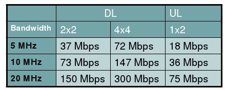
HSPA capability is stated as 14.4Mbps for the DL, so 16QAM @ 15 HS-PDSCH codes and 1.5Mbps UL, so 10ms TTI @ 2 x SF4 E-DPDCH. Obviously the ADSL/cable has to be capable of supporting these speeds as well.

Looking at the AT&T 3G micro cell website, there is also an interesting capability that AT&T have enabled and that is for the customer to be able to configure whether the femto cell hands out to the macro or not. At first I thought this was strange but looking through the FAQ it seems this is a recommendation when a customer experiences dropped calls in their house. As the AT&T macro network does not have the capability to hand into the femto, it is possible that a user initiates a call on the femto and as he moves around the house (towards a window, garden, balcony etc) he hands out to the macro. Then as he moves back into the house the macro signal strength deteriorates and the call drops. So to avoid this happening all mobility is disabled and the user stays connected to the femto until a radio link failure occurs which typically is at a much lower point than a handover threshold.

There is a lot more information about femto cells (from Cisco's perspective at least) including the figures above at the Cisco Live! website.

Wednesday 23 January 2013

Inter Working Function for CSFB


Traditionally support for CSFB requires an upgrade on the legacy MSCs to support the SGs interface. Additionally careful tracking area to location area mapping is required to avoid MT call failures when the UE falls back to a LA that is not the same as the one it registered on or alternatively call handling procedures such as MTRR or MTRF are required with associated upgrades on MSCs and HLRs.

Putting all this together can be an expensive and complicated process which is where the IWF for CSFB comes in. The IWF provides a number of advantages. At the most basic level it is an interface between the MME and the legacy CS network (as shown above). On one side it communicates using the SGsAP with the MME, while at the other side it communicates using MAP to the MSCs and HLRs. At the same time it provides a VLR function where all the LTE UEs are registered against. This is done by creating a "virtual" LA and updating the HLR accordingly. Any MT calls are thus routed to the IWF. At the same time it eliminates the need for TA - LA planning as all TAs can point towards this one "virtual" LA.

For any MO CS calls the UE fall backs towards the legacy network and discovers a "real" LA. This triggers a LA update and subsequently the call is set up.

For any MT CS calls the process is slightly more complicated and is illustrated in the diagram below (click to enlarge).


The call set up flow can be broken down into 4 phases. At phase 1 the incoming call is routed to the IWF and paging is initiated over the SGs interface. This triggers the CSFB procedure. At phase 2 the UE falls back towards a "real" LA and the LA update procedure is triggered. Phase 3 is the clever bit. Here the IWF sends the HLR an SRI to discover where the UE is located (note the the HLR is still waiting for a response to the PRN message from Phase 1). The HLR queries the MSC and responds. The IWF then uses this information to respond back to the original request from the HLR. The HLR then sends this back to the GMSC and the call is routed. Quite clever!

There is however one drawback with the IWF and that is that every call (MO & MT) requires a LAU before the call is set up. This adds approx. 1 to 2 seconds on the overall setup time. With the classic CSFB, the LAU is not performed and as such faster call setup times can be achieved.

To summarise then the IWF has the advantages of..
1. No upgrade to SGs for legacy network
2. No TA - LA mapping/planning
3. No requirement for MTRR/MTRF

..but the disadvantages of:
1. Longer call set up time due to mandatory LAU procedure

Saturday 12 January 2013

4GEE bandwidth @ 10MHz


Back in October 2012 Everything Everywhere a.k.a. EE launched 4G LTE services in the UK. As EE is the merger of T-Mobile UK and Orange UK, it "re-farmed" part of the 1800MHz spectrum these two companies had and used that for it's 4G LTE network.

At the time I wondered how much spectrum they had managed to re-farm for launch and few days back I had some empirical confirmation of how much that is. The log extract below is taken from a WCDMA SIB19 message which is used by the UE for reselection purposes from 3G to 4G.


Part of the information broadcasted in SIB19 is the IE "measurementBandwidth". As LTE allows for flexible bandwidth allocation (1.4, 3, 5, 10, 15 & 20MHz), the UE has to be informed how much bandwidth is used in order to average the RSRP measurements as explained here.

Rather than specifying the bandwidth in MHz, 3GPP uses Resource Blocks (RB) instead. A RB is 180KHz wide, so 50 RBs give us 9MHz. Taking into account the guard bands on each side of the allocated bandwidth we get a total bandwidth of 10MHz.

This means that at least until EE manage to re-farm some additional spectrum they can only offer 50% of the potential maximum LTE throughput. The good thing about EE is that they have quite a lot of 1800MHz spectrum so I imagine they will continuously monitor their 2G traffic (the 1800MHz was originally awarded to T-Mobile and Orange for GSM services) and as soon as possible another 5MHz block can be re-farmed taking the allocated bandwidth to 15MHz and finally 20MHz. As all LTE devices have to support the maximum of 20MHz, this can happen transparently to the end user.

Looking at the additional information in the log extract, we can also see the exact frequency EE are using which is broadcasted as EARFCN 1617. This translates to a centre DL frequency of 1846.7MHz as shown below.

This in turn can be mapped on EEs 1800MHz spectrum holdings (source: OFCOM) as shown below in red.
Taking into account that EE currently use 10MHz for LTE we can also see what is the top theoretical speed their network could achieve. This is shown in the table below.


In the DL using 2x2 MIMO a maximum throughput of 73Mbps is possible. As 4x4 MIMO is not currently implemented by neither operators or UE manufacturers that column is a bit academical. In the UL a maximum throughput of 36Mbps is possible. As a rule of thumb we can say in the best "real life" situation about 2/3 of those speeds is achievable that would make it as DL approx. 50Mbps and UL approx. 24Mbps. Obviously as more users are added to the system the throughput will decrease accordingly.

The final point to note about the log extract is the priority assigned to the LTE layer. This is configured as 6. As the highest priority is 7, EE have left some room for configuring a higher priority layer. This could be a "small cell" layer or if they are feeling confident of obtaining some 800MHz in the upcoming auction they could use that as a "coverage" layer forcing UEs to camp there by assigning it priority 7 and use the current 1800MHz layer as a "capacity" layer.

Saturday 5 January 2013

Mobile Terminated Roaming Forwarding for LTE CSFB


As described in a previous post one of the issues with LTE CSFB is what happens when the UE falls back to the target RAT but the the LA is not same as the one the UE is registered in during the combined attach procedure. This typically occurs on the borders of Location Areas (LA) and Tracking Areas (TA) or when the target layer is 3G and the UE can only acquire 2G (e.g. indoors).

In order to avoid MT call setup failures, operators must implement either MTRR (Mobile Terminating Roaming Retry) described here or MTRF (Mobile Terminating Roaming Forwarding) which will be described in this post.

The signalling flow for MTRF is shown above (click to enlarge) and essentially consists of 3 phases.

Phase 1 and phase 2 are identical to the MTRR signalling flow, with the exception that the network elements involved must support MTRF and signal as such with the applicable IE (MTRF Supported) defined in the specs.

In phase 3 however rather than cancelling the call setup procedure and re-initiating it towards the "new" MSC like MTRR, with MTRF the old MSC is used as a relay and the call setup procedure continues with an additional PRN & IAM procedure. 

So essentially MTRF manages to cut down the signalling flow and the whole MT procedure completes in 3 phases as opposed to 4. This results in a reduced call setup delay and as such better customer experience.

In the final post on the subject I will describe the IWF solution which overcomes the problem of misaligned LA & TA (and a number of other issues) with the inclusion of an additional core network element. 

Thursday 3 January 2013

F-DPCH on a live network (finally)


F-DPCH (Fractional Dedicated Physical CHannel) was first defined in 3GPP rel6 and then further enhanced in rel7 to overcome some soft handover limitations. Once HSDPA is used for the transfer of user data and L3 signalling (RRC & NAS) it allows the multiplexing of up to 10 users on a single SF 256 code for the purposes of sending TPC (Transmit Power Control) commands in the downlink.

As shown in the table below, 3GPP define 10 slot formats which effectively move the position of the TPC bits in the slot.


The obvious benefit in using F-DPCH is the savings in OVSF codes in the DL. Even though the rel99 DPCH uses only a SF256, once the number of simultaneous users increases (it can easily reach 50-60 users in a busy cell) the impact is quite substantial as sixteen SF256 are equal to one SF16. So clearly 50-60 SF256 will block a large portion of SF16 codes that HSDPA requires. With F-DPCH we can multiplex 10 users on one SF256 thus the impact on the OVSF tree is greatly reduced. On top of this there are savings in DL power and DL noise reduction.

It has always struck me as quite strange then, that mobile operators did not embrace the usage of F-DPCH sooner. As I recently discovered though, things are starting to slowly change and F-DPCH is being used by some operators.

This particular one was Wind in Greece and specifically in the area of Athens that has been upgraded due to a swap (to Huawei).

As can been seen from the trace below the UE signals to the RNC its support for F-DPCH in the RRC Connection Request. This allows the RNC to configure SRB over HSPA and F-DPCH from the RRC Connection Setup message if the establishment cause is related to a PS session. In this particular network, this option was not used and the SRB was mapped to DCH channels initially.


The actual F-DPCH configuration is activated in the Radio Bearer Setup phase as shown below. At the same time the SRB is also mapped on HSPA channels as this is a pre-requisite for F-DPCH.


Looking at the IE present we can deduce which slot format is being used (0 in this case) and which OVSF code is being used (256,17 in this case).